AMIT 135: Lesson 6 Grinding Circuit – Mining Mill Operator ...
Scale Up in Sizing for Grinding Mills. Scaleup criterion is the net specific power consumption, the power consumed by the mill rotor itself minus all mechanical and .

 WhatsApp)
Scale Up in Sizing for Grinding Mills. Scaleup criterion is the net specific power consumption, the power consumed by the mill rotor itself minus all mechanical and .
Chapter 6 Facility Diagram and Description Introduction Section (a)(3) of the SPCC rule requires that facility owners/operators include in the SPCC Plan a description of the facility, including a facility diagram that marks the location and contents of each fixed oil
A2 HOW TO READ THE WIRING DIAGRAMS Composition and Contents of Wiring Diagrams COMPOSITION AND CONTENTS OF WIRING DIAGRAMS (1) This manual consists of wiring harness diagrams, installation locations of individual parts, circuits diagrams and index. (2) In each section, all specifications are listed, including optional specifications ...
• Is all personal protective equipment (safety glasses with wrap around side shields and complete faceshield) in place? The operator should prepare for grinding by removing all lo ose clothing, jewelry and securely tie back all long hair. • What is the best method and plan for grinding the work piece?
electrical circuit diagram for grinding machine 29 Feb 2012 . Electrical safety for conventional machines such as protective grounding . on electrical circuit diagrams of milling and grinding .
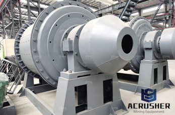
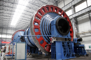
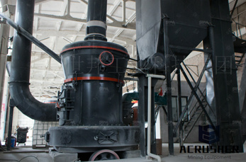
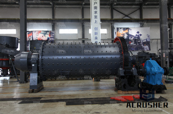
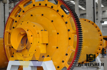
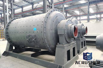
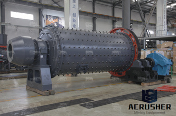
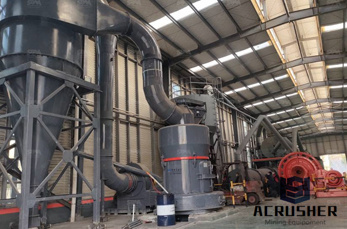
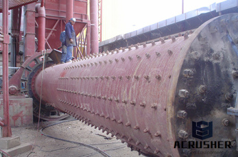
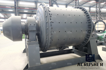
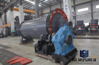
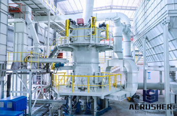
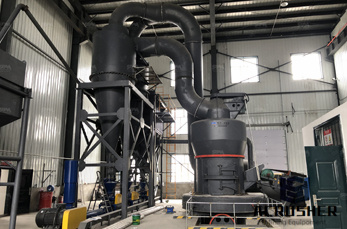
The ball mill is a key piece of equipment for grinding crushed materials, and it is widely used in production lines for powders such as cement, silicates, refractory material, fertilizer, glass ceramics, etc. as well as for ore dressing of both ferrous and nonferrous metals. The ball mill can grind various ores and other materials either wet or dry.
Lathe Machine. A lathe machine is used to design or shape a metal piece accurately. The removal of material from metal is called Machining. Parts of lathe machine Headstock: The headstock is fixed on the machine and it consists of many pulleys, lever, spindle, chuck, and gear box.
Electronic schematics use symbols for each component found in an electrical circuit, no matter how small. The schematics do not show placement or scale, merely function and flow. From this, the actual workings of a piece of electronic equipment can be determined. Figure 3 is an example of an electronic schematic diagram.
grinding machine schematic – Grinding Mill China. grinding mills pdf with schematic diagrams. ... The MTW series milling machine is ideal machine for grinding barite, limestone, mica, talcum, quartz, ...
BASIC SCHEMATIC INTERPRETATION Subcourse Number OD1725 Edition B March 1996 ... manuals in the schematic diagrams of the appropriate equipment. 2. Conductors. Basic to any schematic diagram is the use of ... are usually identified on a schematic diagram by their point of entry into the circuit. 6 OD1725 .
This oversimplified analysis of a single line diagram gives you an idea of the kind of story such diagrams tell about electrical system connections and equipment. Just keep in mind that although some single line diagrams may appear overwhelming by virtue of their size and the wide variety of equipment represented, they can all be analyzed ...
Package Diagram; Profile Diagram; Not all of the 14 different types of UML diagrams are used on a regular basis when documenting systems and/or architectures. The Pareto Principle seems to apply in terms of UML diagram usage as well – 20% of the diagrams are being used 80% of the time by developers. The most frequently used ones in software ...
electrical circuit diagram for grinding machine. electrical circuit diagram for grinding machine BASIC ELECTRIC SYSTEM MAINTENANCE OF CONVENTIONAL 29 Feb 2012 Electrical safety for conventional machines such as protective grounding on electrical circuit diagrams of milling and grinding machines . Business offer
Jul 03, 2014· How to read a schematic, follow electronics circuit drawings to make actual circuits from them. This starts with the schematic for a very simple circuit with just some batteries, resistor, switch ...
This lab apparatus list diagram can be used as a slide or handout to help students to get familiar with lab equipment and their usage easily. It is editable in vector format allowing glorious export in high display resolution.
ELECTRICAL AND ELECTRONICS DIAGRAMS USAS 1966 USA STANDARD APPROVED includes the following: 151 Scope 152 Definitions 153 General Infonnation 154 SingleLine Diagrams, General 155 SingleLine Diagrams (Electronics and Communications) 156 SingleLine Diagrams (Power Switchgear and Industrial Control)
A schematic diagram of the Knelson Concentrator is shown. It has gone through several modifications, since its introduction as a semibatch unit in 1982 to a continuous mode of operation (Knelson and Jones, 1994). The equipment essentially has a ''V'' shaped cone with a series of parallel riffles and many small holes inside the cone.
Process flow diagrams (PFDs) are used in chemical and process engineering. These diagrams show the flow of chemicals and the equipment involved in the process. Generally, a Process Flow Diagram shows only the major equipment and doesn''t show details. PFDs are used for visitor information and new employee training.
The schematic ladder diagram resembles a ladder in that it is made up of two vertical lines representing the incoming electrical sources. true The ____________________ diagram not only identifies the electrical components that are in the unit, but also illustrates how the unit works and electrical connections that need to be made.
according to the method of supporting the work .Diagrams illustrating the essential difference in supporting the work between centers and centerless grinding are shown in figure the centerless type the work is supported by the work rest the regulating wheel, and the grinding whell types use plain grinding wheels
Page 23: Exploded Diagram, Htc 800 Grinding Head Exploded diagram, HTC 800 grinding head Parts list HTC 800 grinding head No. Description Art. No. Qty Screw M6S M16X 0 galvanised 10170 Washer BRB M16 galvanised 100 2 Motor 15 kW 1109 Motor 11 kW 80 20 160M .
The objective of this lesson is to provide the details of size reduction methods involved in mineral processing using grinding methods and equipment. ... schematic . diagram of this machine ...
Jan 14, 2016· SCHEMATIC DIAGRAMS. Schematic diagrams show components in their electrical sequence without regard for physical diagrams are used to troubleshoot and install control circuits. Schematics are generally easier to read and understand than wiring diagrams.
Start studying Instrumentation Drawings Level 2. Learn vocabulary, terms, and more with flashcards, games, and other study tools. Search. ... These are used to show the interconnection of equipment and components in a system. Line diagrams. ... Schematic diagrams. These illustrate the operational layout of a system, including its piping, valves ...
WhatsApp)